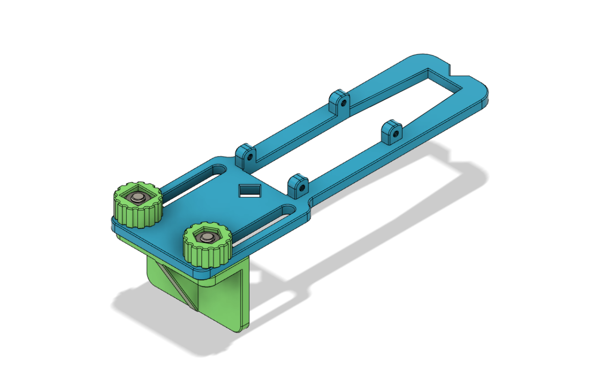
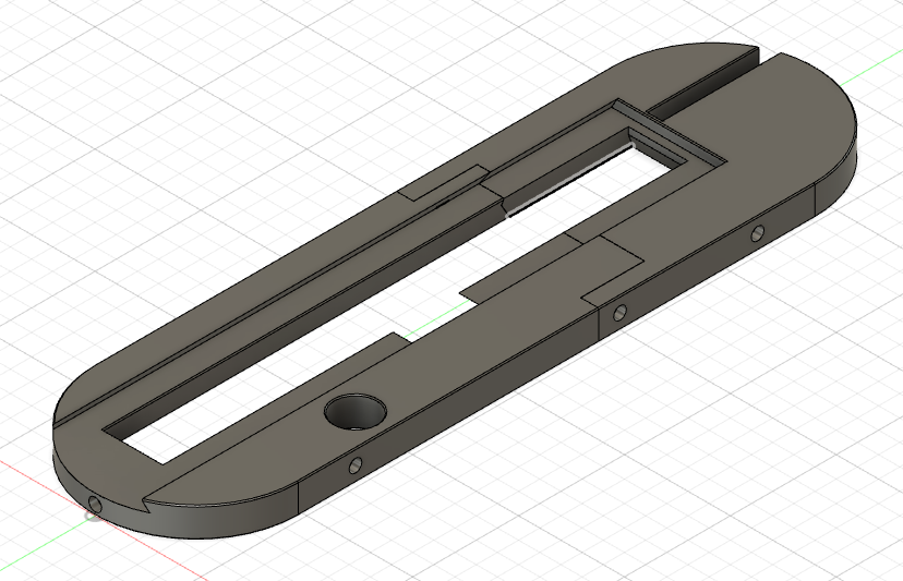
When looking for a pocket hole jig, I had difficulty choosing between the various versions Kreg offers. On the one hand, I wanted the Mini because it is the smallest jig that can get into tight places, and is very cheap. On the other hand, I wanted the jig to have a nice fence for easy, repeatable pocket holes. I decided to design my own fence system for the Kreg Jig Mini, which, I believe, is more flexible than the fence that comes with the Kreg Jig 320. The fence I designed allows for a greater range of adjustability and features alignment windows for precise positioning of the jig on a drawn pencil line.
Category: Tools
Ultimate 3D Printed Table Saw Throat Insert With Dovetailed Zero Clearance Strips
I designed an all-in 3D printed table saw throat insert. It features changeable dovetailed zero clearance strips that are easy to make from 1/4″ birch plywood. The insert allows full range of movement of blade and splitter (height and tilt angle). It has leveling feet for perfect alignment with the table surface, a safety tab, and fine fit adjustment screws. It can be printed on most common household 3D printers. While it is tailored for my particular table saw, I’m hoping that the design can be tweaked to fit other left tilting saws.
Making copper tipped chuck retention bolts
My wood lathe has no allowance to lock the chuck on the spindle, and yet that is a very useful feature, which gives you, for example, the ability to sand in reverse rotation. The spindle is threaded all the way to the shoulder. My chuck is a OneWay Stronghold, and its spindle adapter has two M8 threaded holes for securing it on a spindle with grub screws. The problem is that steel grub screws would damage the threaded spindle when tightened.
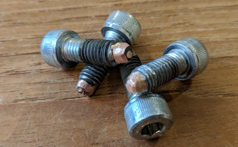
I thought I would make copper-tipped steel bolts that could be adequately tightened without the danger of damaging the spindle thread. I already had some M8 socket head bolts, and figured that I could TIG braze a piece of copper on their tips. I found it impossible to do because the copper piece melts before the silicon bronze filler. Copper’s melting point is just 1080°C, while ERCUSi filler melts at around 1800°C.
Then I tried a different approach, and it worked very well. I first “tinned” the tip of the screw using the silicon bronze filler, and then, while maintaining the silicon bronze puddle, switched the filler to copper wire (I used gauge 12 single strand electrical wire). The copper flowed very nicely into the silicon bronze puddle, and I was able to build up a big blob of copper on the tip of the bolt this way.
I used 30A DC Pulse setting, with 33 pps, 33% on time, 33% background, as recommended by Jody Collier. I held the bolt in vise grips and built a dam around with aluminum foil, to keep the shielding gas around the piece.
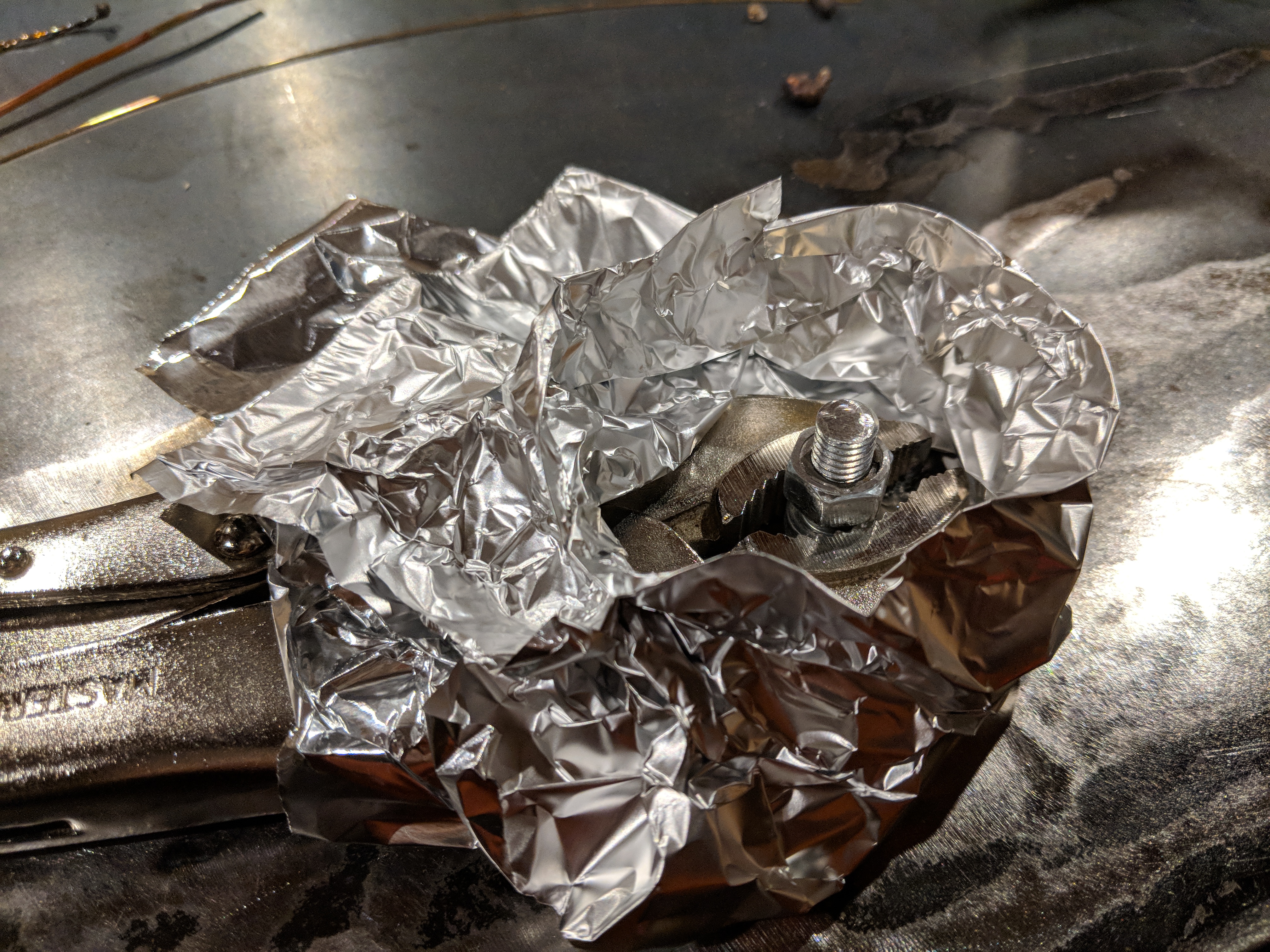
I threaded a nut around the bolt before brazing the tip on, so that it would be easier to grind the blob down, knowing that it does not impede the threading.
I am quite pleased with the results. I wonder how long it will take for the copper tips to be worn off. Building the copper up again should be fairly easy, when the do wear off.